Project AKO
HomeNews
AKO@sf.net
AKO Components

AKO components are the pieces that do all the dirty work of interfacing with the outside world. They consist of a microcontroller with any associated hardware for it's task, and appropriate firmware. The components are coordinated over the AKONET by the central controller.
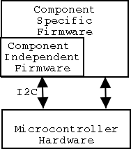
The firmware for the components is broken into two parts, the Component Independent Firmware (CIF), and the Component Specific Firmware (CSF). All components share the same CIF layer. The CIF contains the AKONET stack. The CIF also handles some application level messages that are common across all components. Additionally, the CIF contains startup routines, the interrupt service routine (ISR), and utility routines. The CSF is unique for every component. The CSF handles application level messages specific to that component, and manages all the hardware required to accomplish its task. The CSF utilizes routines in the CIF for all AKONET access.
Components were originally implemented on the PIC16C64A. Currently, components are implemented on PIC16F877's. The CIF features a fully multithreaded AKONET stack, allowing components to continue processing while both sending and receiving messages.
At present, the following components have been implemented: digital I/O, analog input, stepper motor control, DC motor control with encoder feedback, and a differential drive mobile base unit.
The digital I/O component features 24 I/O lines, grouped as three 8-bit ports. Each line is individually programmable as either an input or an output. In addition to polling, interrupt on change is supported to reduce the load on both the main controller and the AKONET.
The analog input component features 8 12-bit D/A units. In addition to polling, several types of interrupt are supported to reduce the load on the main controller and the AKONET. These types of interrupt are: interrupt on delta, timed interrupt, and interrupt on threshold. Attachments that allow the analog input to serve as a light sensor and as a temperature sensor have been built. Dedicated temperature and light sensors that can be calibrated to provide linear response to their sensors are planned.
The stepper motor component allows stepper motors to be stepped in either full-wave or half-wave configurations.
The DC motor component allows DC motors to be driven. A PWM signal fed through an H-bridge is used to control the direction and speed of rotation. The encoder count can be polled, or the component can be instructed to revolve the motor through a specified number of encoder clicks.
The Mobile Base Unit (MBU) component is a differential wheel drive chassis that the MCB, batteries, and various components can be loaded onto to create a mobile robot. The MBU component understands a variety of commands, including forward, backward, turns, and turns in place. Encoder feedback is used to track MBU movement, and to keep the movement straight.